
Lincoln Experimental Satellites
Since 1958, with the passive communication satellite put into orbit through Project West Ford, MIT Lincoln Laboratory has made monumental achievements in exploiting space for reliable long-range radio-frequency (RF) connectivity. These accomplishments have created the architectural framework and technology foundation for the nation's military satellite communications (MILSATCOM) systems while influencing many civil communications satellites. By adopting a complete, systems-level approach addressing both space and terrestrial segments, Lincoln Laboratory has time and again developed and transferred advanced solutions to difficult, critical communications challenges.
Each of the Laboratory's RF space-based communications efforts has contained four important elements:
- Architectural frameworks addressing system-level issues
- Technologies critical to mitigating system-level issues
- Proof-of-concept developments and testing in representative environments to measure system performance and implementation complexity
- Technology transfer to sponsors and their industry partners
This website covers the Laboratory's RF SATCOM research and development accomplishments from 1963 through 1980. During this time frame, eight active Lincoln Experimental Satellites (LES) and adaptive satellite antennas were developed. These efforts demonstrated initially that satellites could provide long-range communications of unprecedented reliability and later that such advantages could be extended to mobile users and subsequently to users needing robust connectivity. The transfer of advanced technologies validated in this period enabled three major types of military RF SATCOM systems — high-capacity voice and data relay, mobile user communications, and highly protected connectivity — and influenced many of the concurrent civil communications satellites.
The material on this site has been partitioned into the following chronological time frames:
The information for each time period indicates some of the challenges addressed, advances realized, and technologies matured and highlights the resulting impacts on subsequent space systems.
Since the LES period, Lincoln Laboratory has continued to address evolving challenges to reliable, long-range military communications. The Laboratory has developed innovative communications architectural concepts and critical technologies to extend RF SATCOM protection and wideband capacity and to demonstrate multiple-system resiliency. Effective transfer of concepts and associated technologies have remained integral parts of the Laboratory's efforts.
Initial Active Satellites (1963-1965)
By 1963, technologies to enable active communications satellites were emerging, and the U.S. Department of Defense had requested that Lincoln Laboratory develop proof-of-concept systems to address military needs for reliable, long-range connectivity. The initial objective of this request was to demonstrate practical military communications with Lincoln Experimental Satellites (LES) and companion Lincoln Experimental Terminals (LET). Unlike passive satellites, which only reflect received signals, the active LES satellites would amplify received signals before retransmitting them back to Earth. By offering higher downlink received signal levels, actively transmitting communications satellites enabled the use of transportable-class LETs instead of larger capital-asset ones — an advantage for deployed military field use.
LES-1 and LES-2
In February and May 1965, respectively, Lincoln Laboratory and the U.S. Air Force launched two super-high-frequency (SHF) satellites, LES-1, and LES-2, and fielded three corresponding terminals (LET-1, LET-2, and LET-3). These active communications satellites were the first to use X-band, part of the SHF range of the electromagnetic spectrum. Relative to higher frequencies, X-band maintains better performance in rain while still accommodating high-throughput signals like imagery and high-definition video.
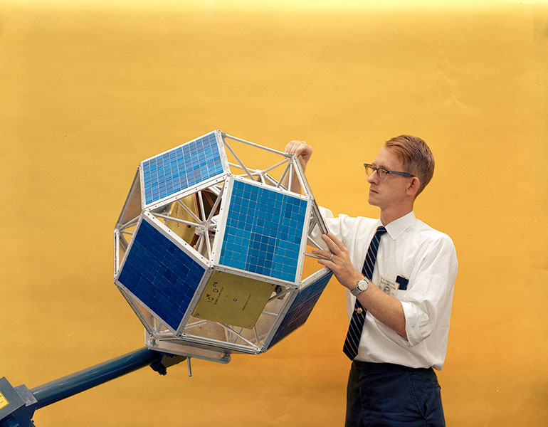
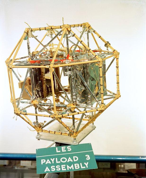
Built as identical twins, LES-1 and LES-2 had a polyhedral body shape, weighed approximately 80 pounds, and were spin stabilized. On the sides of the polyhedron were solar cells for power and Earth and Sun sensors for pointing. The downlink signal (from a satellite to a terrestrial terminal) was generally the weaker link, so considerable effort went into developing reliable, high-efficiency transmitters in the downlink portion of the SHF frequency band. Each satellite's communications transponder translated signals received at the uplink frequency to the downlink frequency after passing the signals through a 20 MHz-wide filter at an intermediate frequency and through an amplitude hard limiter. In response to measurements by the visible-light sensors of the Earth's position, an innovative autonomous electronic antenna-switching system would connect one of eight SHF horn antennas on the corners of the polyhedron to the transponder. A magnetic attitude control system (pulsed electromagnets working against the Earth's magnetic field synchronously with sensor outputs) kept the satellite's spin axis oriented perpendicular to the line of sight with the Sun to avoid thermal problems.
LET-1 was a complete, self-contained, transportable ground terminal capable of testing and demonstrating evolving communications techniques in realistic environments. The terminal included many innovations key to subsequent successful operational systems: advanced modulation and demodulation (including spread-spectrum frequency hopping over the 20 MHz transponder bandwidth to provide a level of protection against interference), state-of-the-art convolutional encoding and sequential decoding to detect and correct errors in the received data stream, sensitive acquisition and tracking techniques, and highly effective vocoders for speech compression and reconstruction.
LET-2 and -3, each consisting of only the signal processing van (thus not incorporating a transmitter or an antenna), were built concurrently with LET-1. One LET was used with the Laboratory's Project West Ford SHF terminal, and the other was transferred to the Army Signal Corps for service with SHF terminals at Camp Roberts, California, and Fort Monmouth, New Jersey.
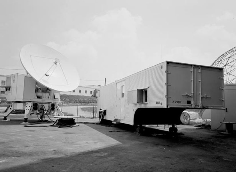
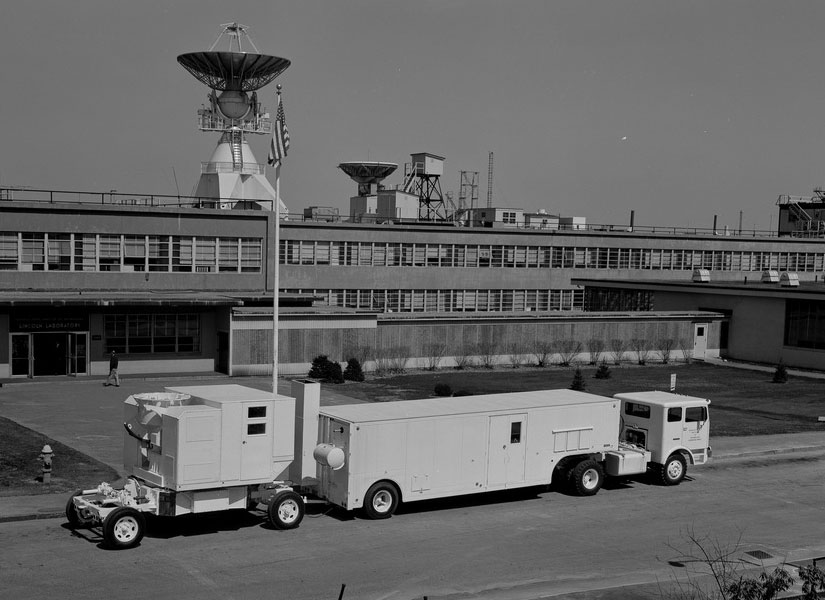
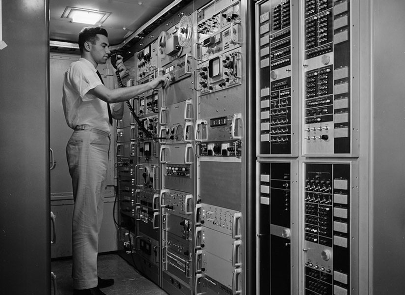
LET-1 is set up in its operational configuration (left) and transportable configuration (middle); an operator controls the terminal equipment racks (right).
LES-1 and LES-2 were launched separately on Titan III-A booster rockets, which were capable of carrying such spacecraft to inclined circular orbits at an altitude of about 2,800 km. To reach a higher altitude, allowing tests that would better represent operational MILSATCOM systems, LES-1 and LES-2 were each equipped with a perigee (point of closest approach to Earth) kick motor, a solid-fuel rocket that would place the satellite in an inclined elliptical orbit with an apogee (point farthest from Earth) of 15,000 km. Unfortunately, a subsystem failure of the onboard rocket left LES-1 in a circular transfer orbit at an altitude of 2,800 km. After this failure, engineers working on LES-2 revised the ordnance circuity responsible for separating the satellite from its Titan carrier. The LES-2 launch a few months later was a success, with the satellite placed into the intended elliptical orbit.

Despite its undesirable launch outcome, LES-1 demonstrated for the first time in orbit a small, all-solid-state transmitter generating SHF power at X-band. This satellite also introduced other innovations, such as a switched antenna pointing system to boost signal strength and a magnetic spin stabilization system to point the satellite in the appropriate direction for better thermal control. The low-altitude orbit of LES-1 did not allow sufficiently long, concurrent visibility from multiple terminals for realistic operational SHF communications scenarios, but these important experiments were successfully conducted with LES-2.
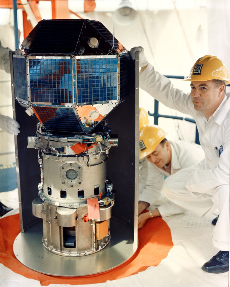
In 1967, at the end of their intended lifetime, LES-1 and LES-2 shut down their transmitters. For the next 45 years, the satellites tumbled silently in orbit. But in 2012, amateur radio operators detected a telemetry signal from LES-1 at a UHF frequency of 237 MHz. (While LES-1's communications experiments involved the use of the wider-bandwidth SHF, UHF was incorporated as an alternative path for telemetry and command functions because these lower-data-rate functions could use very broad-beam satellite antennas — a potentially important capability in case of a spacecraft tumbling due to attitude control issues.) How could LES-1 spontaneously resume transmissions after so many years of silence? One possibility is that LES-1 experienced an electrical short (caused by the batteries or circuity degrading over time), allowing power from the solar cells to directly reach the transmitter.
LES-4
In December 1965, LES-4, the last of the Laboratory's initial group of active experimental SHF communications satellites, was launched. Built to fulfill the goal of placing a communications satellite in geosynchronous orbit, which allowed continual viewing of a large segment of the Earth, LES-4 improved upon the LES-1 and LES-2 design. The approximately 115-pound satellite had additional solar cells, with Earth and Sun sensors, as well as SHF horn antennas arranged cylindrically around the intended spin axis, rather than on the corners of a polyhedron body. With this layout conferring improved stability, the satellite could point somewhat higher-gain antennas toward the Earth. While its SHF transponder was identical to the ones on LES-1 and LES-2, the LES-4 electronically switched SHF antenna system to de-spin the antenna beam was more sophisticated. LES-4 also carried an instrument for measuring spatial and temporal variations of the energy spectrum, in five energy ranges, of trapped electrons encountered in orbit. This instrument was included to provide information of scientific interest and for use in the design of future spacecraft.
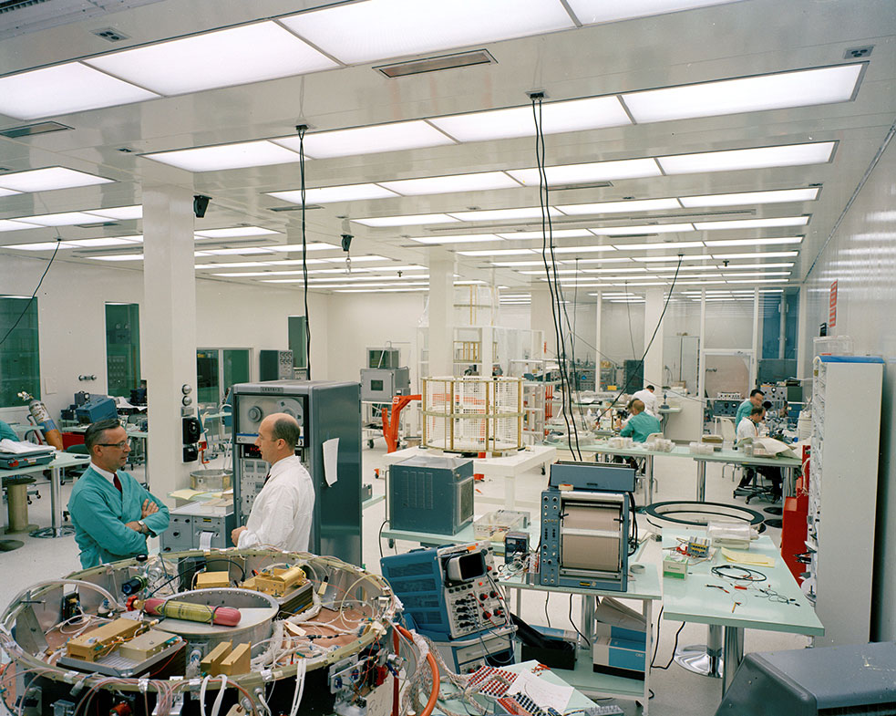
When LES-4 was launched (along with LES-3 ), the Titan-IIIC rocket failed to eject the satellite at the correct circular, near-geosynchronous location. Instead, LES-4 was left in an elliptical transfer orbit from which it could not exit, as it did not have an onboard kick motor as LES-1 and LES-2 did. This disappointment, however, had a silver lining: LES-4's repeated trips between perigee (195 km) and apogee (33,700 km) gave it many opportunities to measure the level of the space radiation environment over a wide range of altitudes. These measurements were shared with the community developing space vehicles, helping them select components appropriate to the radiation environments relevant to the intended orbital altitudes.
The LES-4 communications system worked as well as it could under the handicap of being in the wrong orbit, and experimentation with it furthered the knowledge base concerning SHF satellite communications. For example, while near apogee, LES-4's approximate synchronous-altitude range temporarily permitted the intended SHF communications connectivity among LETs located thousands of miles apart. However, the lower altitude along much of its elliptical orbit and the Earth's rotation did not allow this desired coverage of widely separated terminals to be continual. In October 1968, LES-4 stopped transmitting, and, as with the Project West Ford needles, eventually burned up upon reentry into the atmosphere in August 1970.
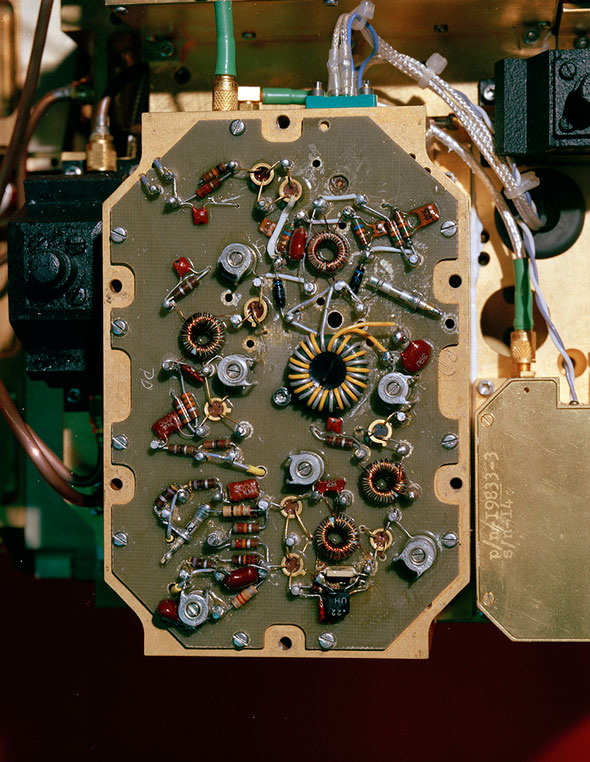
The initial active Lincoln Experimental Satellites — LES -1, LES-2, and LES-4 — and the corresponding LET-1, LET-2, and LET-3 established the feasibility of using active communications satellites for reliable military connectivity to distant locations. They also provided the technology base and operational lessons learned that enabled the successful development and deployment of the Initial Defense Communications Satellite Program (IDCSP) — the first operational MILSATCOM system — and that system's fixed, transportable, and shipboard terminals (on larger vessels). Between 1966 and 1968, 27 IDCSP satellites were successfully launched into orbit. The IDCSP transmitted important reconnaissance photos and voice communications during the Vietnam War. The U.S. Department of Defense used this worldwide military communications system for 10 years, until the more sophisticated Defense Satellite Communications System II (DSCS II) was developed.
Service Extended to Small, Mobile Users (1965-1969)
In 1965, the U.S. Department of Defense (DoD) established the Tri-Service (Air Force, Army, Navy) Tactical Satellite Communications program to evaluate the feasibility of using satellites operating in the military ultrahigh-frequency (UHF) band of 225 – 400 MHz for communications to and from small mobile terminals. Communication links at these lower frequencies would solve the downlink problem — the limited system performance resulting from the fact that high levels of RF power at SHF could not be generated in the satellites of that era. Each terminal needed a relatively large antenna aperture to capture enough of the downlink signal, resulting in a narrow antenna beam that had to be pointed precisely toward the satellite. Small tactical vehicles, ships, aircraft, and infantry could not accommodate such complex antenna systems, especially if the platform carrying the terminal was moving. By contrast, solid-state circuits and spaceborne antennas in the mid-1960s could generate sufficient UHF satellite effective downlink power that relatively uncomplicated low-gain terminal antennas could provide a sizable effective receiving area and a broad beam, greatly simplifying antenna pointing and reducing user terminal cost. Such antennas were particularly appealing for aircraft installation.
LES-3, LES-5, and LES-6
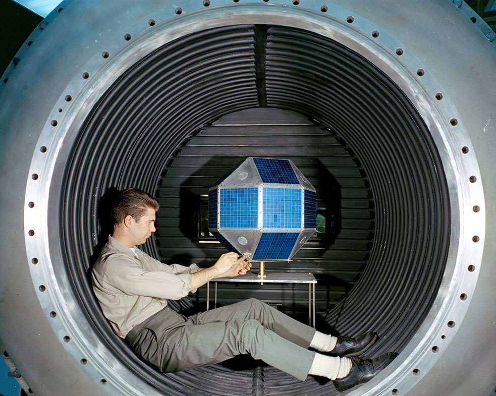
Lincoln Laboratory developed LES-3, LES-5, and LES-6 to operate at UHF. Launched along with the SHF LES-4 in December 1965, LES-3 was essentially a signal generator in orbit. Unlike the other satellites in the series, which both transmitted and received signals, LES-3 solely transmitted signals. Adopting the LES-1 and LES-2 polyhedron platform, LES-3 was built for an experiment to measure the characteristics of the UHF environment. Specifically, LES-3 would help researchers understand signal propagation effects between satellites and airborne terminals over a wide variety of terrains. Much of Earth's surface is mirrorlike at UHF, so electromagnetic waves, especially at lower elevation angles and over flat surfaces, can propagate between a satellite and airborne terminal by a direct path and by paths involving reflection off the Earth's surface. The experiment with LES-3 enabled Laboratory researchers to design modulation and demodulation systems for UHF satellite communications that would not be confounded by such multiple-path propagation effects. LES-3 was destroyed upon reentry into the atmosphere in April 1968.
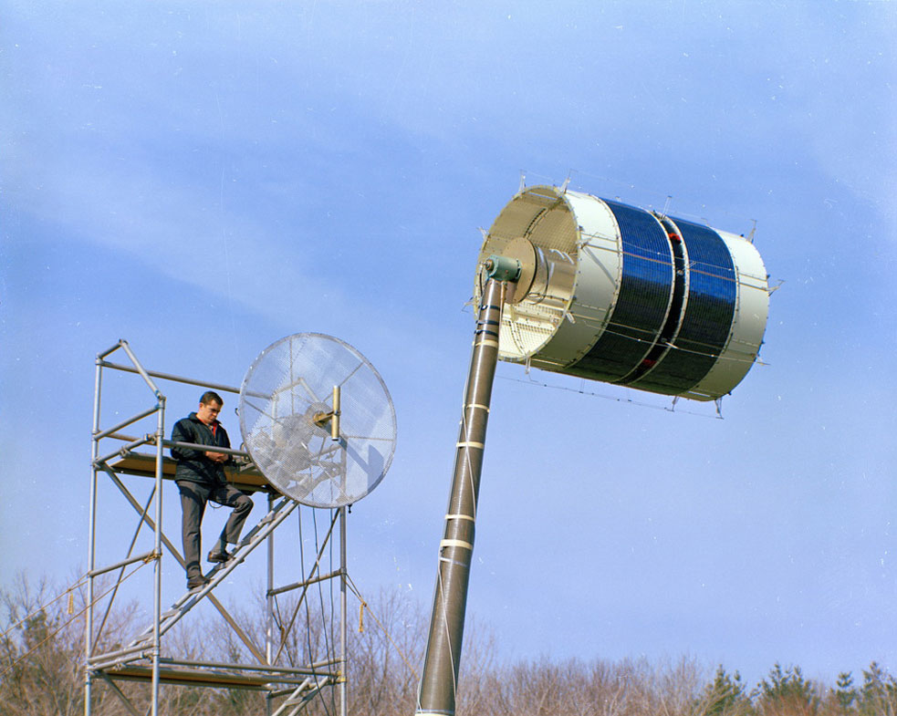
Both LES-5 and LES-6 were launched on Titan-IIIC boosters in July 1967 and September 1968, respectively. The satellites were cylindrical in shape with a series of UHF antennas mounted along their circumference, solar powered, and spin stabilized around an axis perpendicular to their near-equatorial orbit plane. Each satellite included a broadband, frequency-translating UHF-to-UHF transponder and an autonomous antenna switching system to connect the more Earth-facing UHF antenna(s) to the transponder as the satellite rotated. They incorporated Laboratory advances in terminal signaling and efficient access control techniques, specifically the robust Tactical Transmission System (TATS) and the demand-assigned Terminal Access Control System (TACS).


Using LES-5 and LES-6, tactical Army, Navy, and Air Force terminals could readily communicate. The demonstrated feasibility and affordability of UHF communications for size-constrained user equipment prompted the DoD to procure large quantities of UHF terminals and put UHF satellites and TATS and TACS systems into production. LES-5 and LES-6 have influenced several generations of operational UHF military satellite communications systems: the Fleet Satellite Communications System (FLTSAT), Ultrahigh-Frequency Follow-on (UFO) satellite system, and Mobile User Objective System (MUOS). The Extremely High Frequency (EHF) packages on the UFO spacecraft and the Ka-band feeder links on MUOS were influenced by additional Laboratory accomplishments involving highly protected signaling .
Both LES-5 and LES-6 were officially discontinued in 2002, after more than 30 years in operation.


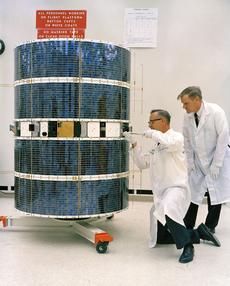
Engineers check the LES-3 (left), LES-5 (middle), and LES-6 flight unit spacecraft assemblies.
Adaptive Spacecraft Antennas (1970–1972)
By the late 1960s, the vulnerabilities of the operational UHF and SHF SATCOM systems to intentional interference were apparent. Although UHF was the focus for LES-5 and LES-6 because it would enable affordable communications for mobile platforms, SHF, because of its larger bandwidth allocations, was more desirable for military applications requiring higher data rates and/or increased resistance to intentional interference. Therefore, Lincoln Laboratory returned to the SHF band in an initial effort to enhance robustness.
LES-7
The antenna systems on the earlier SHF satellites had been small in terms of wavelength, and their beams were much larger than needed for Earth coverage from their orbital altitude. The next level of sophistication in SHF satellite communications that Lincoln Laboratory investigated was an antenna system with an uplink beam that could provide focused coverage to selected regions of Earth, thereby reducing the receiving (uplink) sensitivity in directions from which jamming or other interference may come. In this approach, a multiple-beam antenna (MBA) contains many separate antenna feeds to form a dense set of narrow pencil beams covering the Earth. The signals from this collection of beams are adjusted in amplitude and phase ("weighted") and combined to approximate the desired antenna pattern.
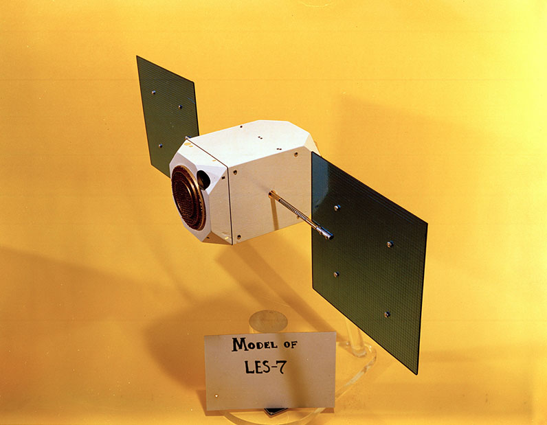
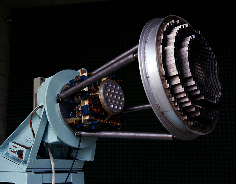
The Laboratory began a program to demonstrate in orbit a 19-beam adaptable uplink antenna for reception at SHF (with an Earth-coverage horn used for downlink transmission). However, in early 1970, the government and the Laboratory decided that the critical MBA technology could be adequately developed and verified via ground-based (versus on-orbit) testing and qualification. A few years later, the Lincoln Laboratory MBA innovation found application on the third generation of the operational Defense Satellite Communication System (DSCS III), where it was incorporated, almost without change, as the primary antenna system — a successful example of effective technology transfer to reduce development risk on a major Department of Defense procurement. The MBA approach was also subsequently utilized on the Wideband Global SATCOM system, the follow-on to the DSCS III wideband voice, data, and image relay system.
New Architectural Concept for Robust Communications (1970-1980)
By the late 1960s, national-level studies had identified emerging Cold War threats that could potentially disrupt the critical strategic-communications connectivity provided by the existing SHF and UHF SATCOM infrastructure. Motivated by these studies, Lincoln Laboratory in 1970 initiated the development of a game-changing architectural concept and enabling technologies for highly reliable and survivable strategic communications. The concept and enabling technologies would also provide the increased bandwidth necessary for extending emerging video services and sensor information to mobile users.
LES-8 and LES-9
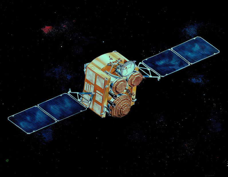
Two experimental satellites emerged from this development: LES-8 and LES-9. These three-axis-stabilized satellites were the last and most sophisticated of the LES series. Along with two Navy Solrad satellites, they were launched in March 1976 from Cape Canaveral, Florida, by a Titan-IIIC rocket and placed into a geosynchronous-altitude, circular, ecliptic-plane orbit, with LES-8 and LES-9 approximately 90 degrees apart. The groundbreaking achievements of these satellites included demonstrating paths forward for reliable communications among mobile users in highly contested environments, for expansion into very wideband RF SATCOM systems, and for a variety of other innovative applications of government and civil interest.

The Laboratory's architectural concept for LES-8/9 included several first-time SATCOM applications. The satellites communicated with each other via intersatellite links (crosslinks) at Ka-band (37 – 38 GHz range) and with terminals operating on or near the surface of the Earth at both Ka-band and UHF. The Ka-band portion of the spectrum was appealing because of the abundant bandwidth that could accommodate very large numbers of simultaneous users and support extremely wide bandwidth applications. (For example, current UHF satellites support <50 MHz of bandwidth, while future Ka-band satellites could support >2,000 MHz, which would provide 40x greater bandwidth for a given coverage area.) The overall experimental system supported assured communications between small, mobile terminals at data rates ranging from teletype (75 bps) to vocoded voice (2,400 bps) and computer data exchange (19,200 bps), with previously unreached levels of interference resistance.

The direct communications links between LES-8 and LES-9 demonstrated significantly enhanced system-level physical robustness; with these crosslinks, the execution of a strategic communications scenario would not depend on the survivability of terrestrial relay facilities. The experiment's crosslinks were the first to have full-duty-cycle operation, digital implementation, and multiplexing of several information streams. Desired RF frequencies for such crosslinks would be the oxygen-absorption bands near 60 GHz, or, alternatively, the crosslinks would operate at optical frequencies. Optical communications were viewed by Lincoln Laboratory as too immature in the 1970s, as was RF test equipment above 40 GHz. Hence, Ka-band was used for the demonstration of the crosslink capability.

The Ka-band links from LES-8/9 to command centers (the more physically survivable of which would be Airborne Command Posts, or ABNCPs) and submarines (via mast- or periscope-mounted antennas) provided multiple GHz of bandwidth for spread-spectrum modulation. Such modulation enabled state-of-the art interference-rejection for force-direction messaging and for conferencing among command authorities. The receivers, transmitters, and antennas developed for this experiment were the first at any frequency above 8 GHz for space-terrestrial communications. Onboard signal demodulation and remodulation and switching of digital streams on LES-8/9 further enhanced signal robustness by removing uplink interference and noise that would waste a portion of downlink power in a typical transponder-based communications satellite. The Laboratory recognized that the more numerous airborne force elements, such as strategic bombers, would also benefit from Ka-band links; however, recapitalizing from their installed UHF systems with hemispherical antenna beams to Ka-band systems with directive antennas would be expensive and lengthy. Therefore, Ka-band-to-UHF crossbanding was included in LES-8/9 to permit many force elements to remain at UHF; new modems contained enhanced downlink signaling for increased rejection of any spaceborne interference and an innovative code-division multiple-access uplink technique to efficiently handle hundreds of concurrent report-back messages.
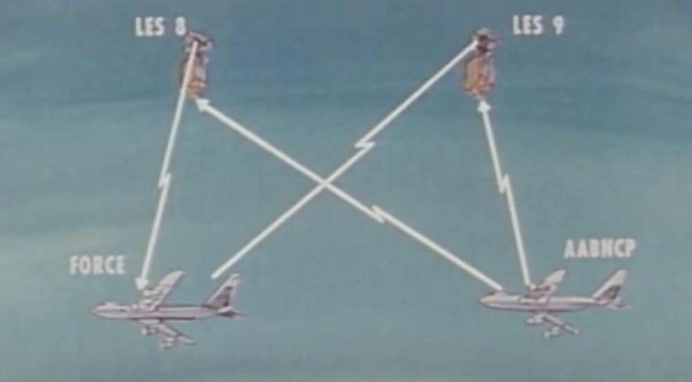
Additional satellite resiliency features included autonomous on-orbit operation utilizing a low-drift-rate third-generation gyroscope from Draper Laboratory and a radiation-hardened power source from the U.S. Department of Energy.
Lincoln Laboratory, the U.S. Air Force, and the U.S. Navy developed proof-of-concept terminals to work with LES-8/9. Airborne demonstrations were conducted with an Air Force Research Laboratory (AFRL) aircraft incorporating both Ka-band and UHF terminals so it could emulate ABNCPs and both Ka-band and UHF-equipped force elements to experimentally evaluate the advantages of the new strategic communications concepts and technologies.
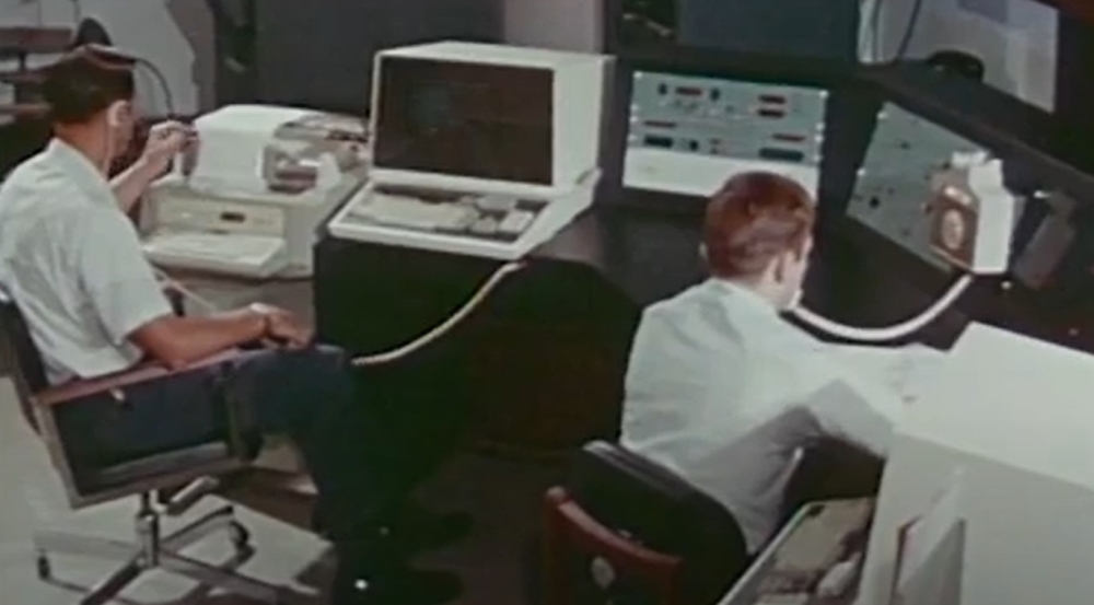
The LES-8/9 program also developed human-interface control panels to allow communications configurations (or bus functions using a similar panel) to be rapidly established or changed without an operator having extensive knowledge of the satellite's design. The viability of controlling a strategic communications scenario only from an ABNCP was demonstrated by connecting these control panels to a terminal on the AFRL test aircraft and executing force-direction, command conferencing, and report-back functions while the controlling aircraft flew in the Artic. This test was a major demonstration of the robustness of the envisioned architecture.
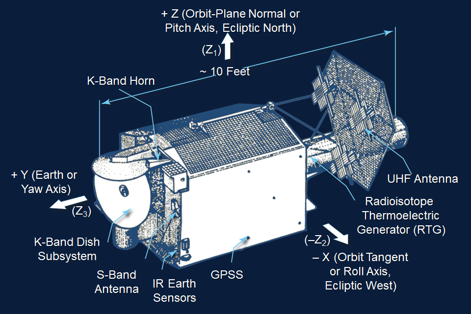
LES-9 and LES-8 had similar arrangements, except LES-8 was rolled 180 degrees around the Earth or yaw axis (rotation around a vertical axis) so that its crosslink antenna could point to LES-9. The satellite is a three-axis controlled platform with a longest dimension of 10 ft and a weight of about 1,000 lbs. The attitude control system incorporates a gimballed momentum wheel, Earth and Sun sensors, and a gas-propulsion system to offload the momentum wheel and to accommodate changes in the station-keeping location. The Earth-facing end of the satellite contains an S-band antenna for command and telemetry; Ka-band horns for Earth coverage; and a Ka-band dish system, which could support higher-data-rate command-center conferencing to theater-sized areas or a crosslink to LES-8. The UHF antenna is an array of crossed dipoles over a ground plane mounted at the back of the satellite (as seen from the Earth), along with a pair of radioisotope thermoelectric generators (RTGs), which each produced about 155 W of power at the beginning of life. Both LES-8 and LES-9 were among the first satellites to demonstrate the use of RTGs, which provided more reliable power over the long term than the combined solar cells and chemical batteries powering previous LES generations.
The LES-8/9 on-orbit experimentation phase was highly successful, validating a viable path forward for protected MILSATCOM. The use of wide-bandwidth allocations available at Ka-band frequencies and above, the on-board signal processing framework, spread-spectrum techniques, frequency crossbanding approaches, and crosslink concepts were incorporated into generations of future military and civil satellite communication systems — including the Military Strategic and Tactical Relay (Milstar) I, Milstar II, and Advanced Extremely High Frequency (AEHF) systems in use today. Many were also included in NASA's Advanced Communications Technology Satellite, which was a pathfinder for today's large number of Ka-band civil communications satellites.
LES-8 and LES-9 were decommissioned in 2004 and 2020, respectively. With 44 years of successful service, LES-9 holds the record as the longest continuously operating satellite in U.S. history (when a decade or less of operation was typical for satellites of this era) — and likely the world.